Mechanical Design Roadmap
Background
After coming up with the general design and ordered most of the parts for the project, there is a need to design a customised shell to hold all the component. To fulfill the constrain of the project, it is required that the shell can be easily hold by the user with one hand. After some discussion within the group, 3D printing the pen shell is chosen as the best way to create the shell. This section will include the road map of the mechanical design with reference of picture of the Solidworks models and the actual printed models.
Initial Design: version 0
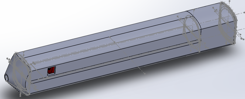
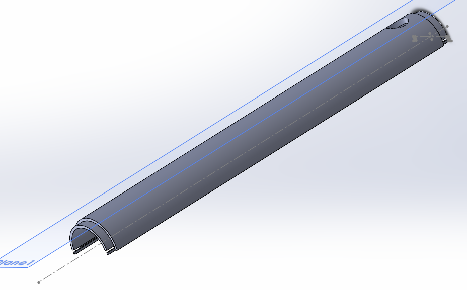
To minimized the size of the pen and to ensure there are ways to open the pen shell to debug the program, a sliding mechanism is used to merge the top and the bottom shells. And to secure the horizontal position of the pen shell, grooves are made at the beginning and the end part of the pen shell body and will be secured with the pen tip and the pen cap. The Solidworks fully assembled model is shown down below. The holes on the shell are made for pushbuttons.
The picture down below is the top shell model, from this it can be observed that there are two small slots located on the inner side of the pen body. For the bottom shell, there are two matching slots. By using these two slots, the top and the bottom pieces will be able to slid into together and then secured by the tip and the cap pieces. With this design, the pen can be disassembled easily for debugging or maintenance purposed.
Version 1
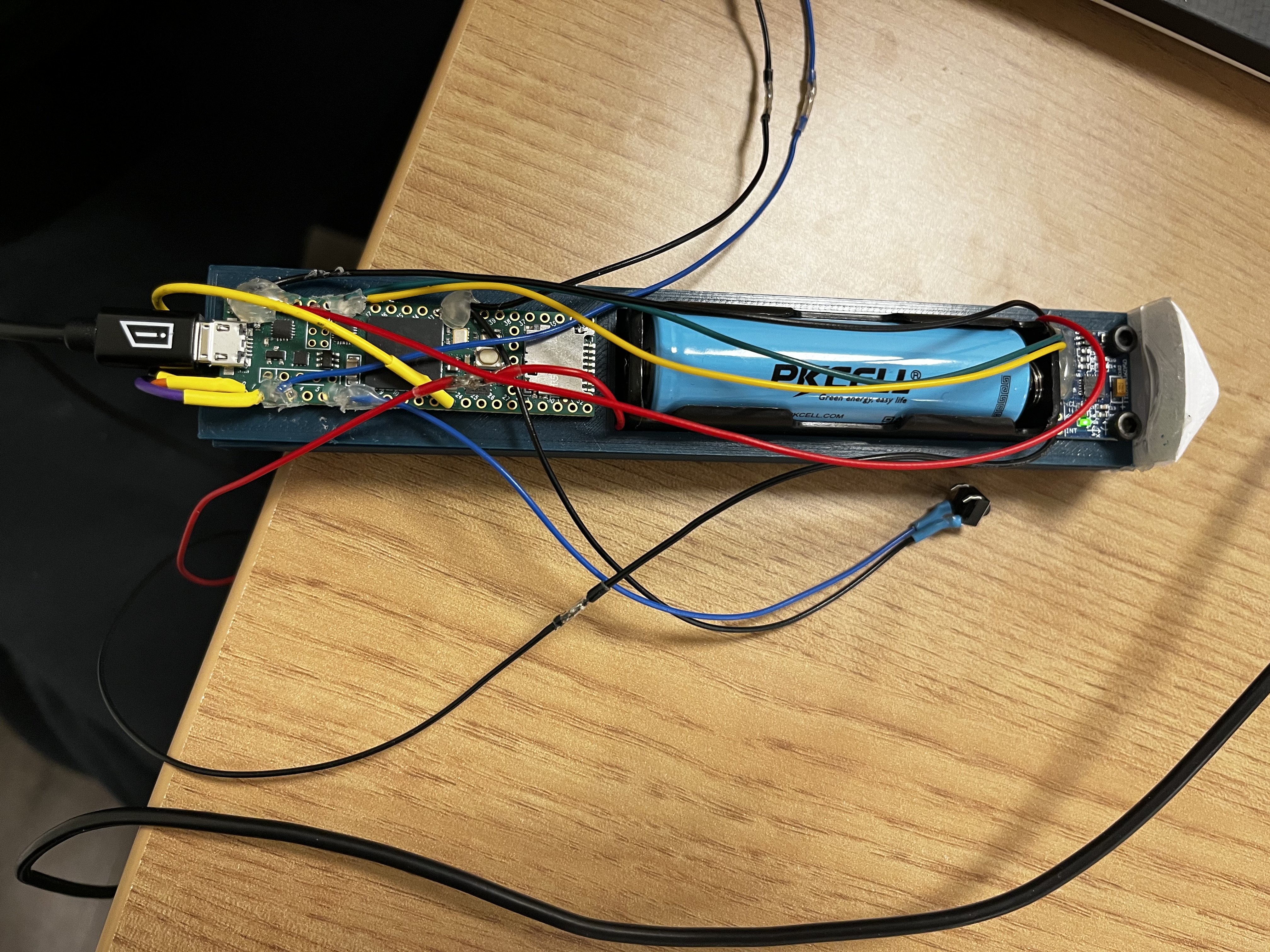
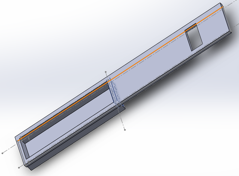
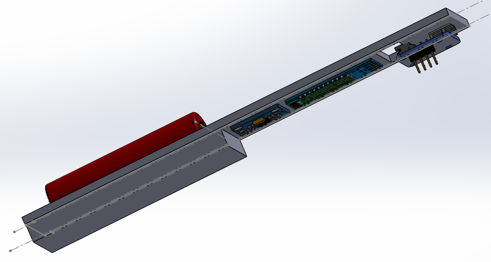
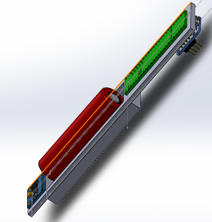
Even thought the initial design has a rally nice mechanism that allows the user to easily disassemble the body, it does not have a good way of securing all the components inside of its body. Especial, the project heavily relies on reading the relative position data from the MPU sensor base on the user’s movement. There need to be a way to secure the MPU sensor in a fixed position inside of the pen shell body. In addition, the MPU should be positioned horizontally relatively to the user’s hand when it is being held. To encounter all the points mentioned earlier, the group has decided to include a base board in the pen sell for mounting all the parts in the correct orientations in a stable way. The base boar Solidworks model is shown down below, along with the assembly version with all the components. To minimize the size of the pen, components are mounted on both the top and the bottom of the base board. The rectangular hole left on the board is used to allow the space for wirings to connect the components located on both sides of the base board.
Version 2
To reduce the length of the pen body, as well as simplifying the assembling and mounting difficulty, the rectangular wiring hole is eliminated in this version. And the MPU sensor is moved to the very beginning of the board.
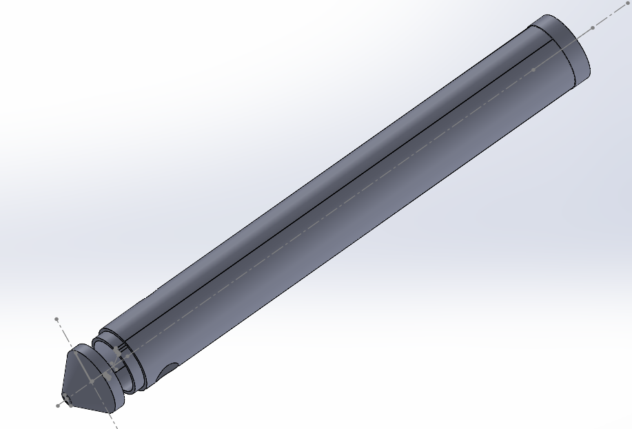
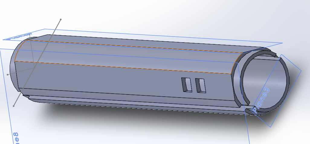
Then the pen shell body is modified with added two flat surfaces on the top shell to direct the user to hold the pen in the correct orientation. The groves are kept from the old design. And the pen body will be secured similarly to the old design by using the pen tip and cap pieces. The picture below is the Solidworks model of the top and bottom piece of the pen body.
Version 3
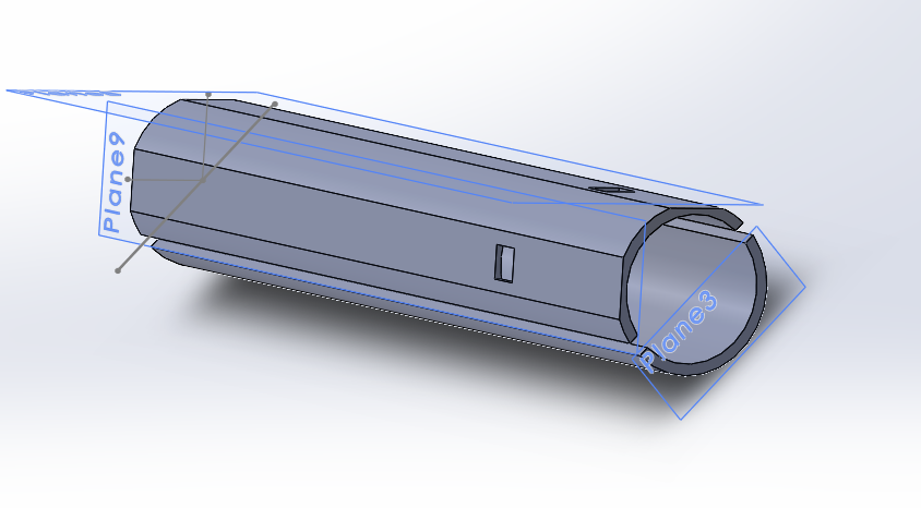
At this point, the initial design was printed, and it failed. The failed print is shown in the picture down below. And the group quickly realized some of the designs are too detailed to print with the 3D printer. As a result, in this design the grooves at the beginning and the end of the pen body are removed. The picture down below is showing the shell body without the grooves.
Also, the positions of the pushbutton are moved from one side of the pen body to both sides.
Version 4
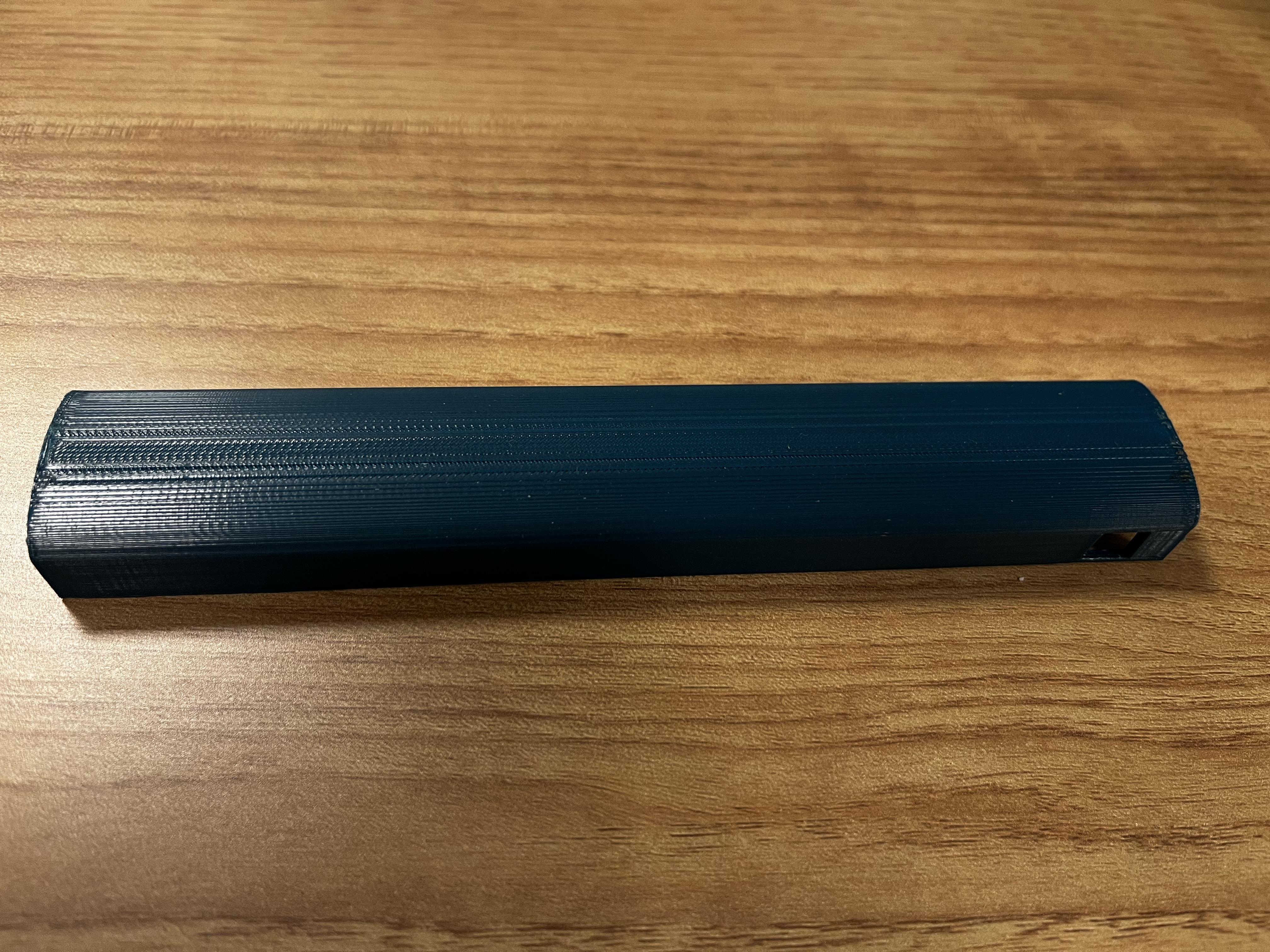
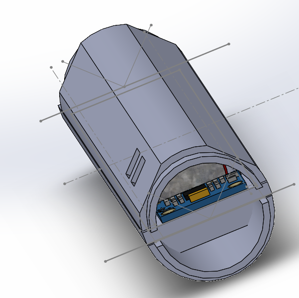
Considering decreasing the difficulty of assembly and optimizing the design to reduce the pen size, the bottom shell shape is changed from a half circle to a square shape with a flat curved bottom. This is shown in the picture down below.
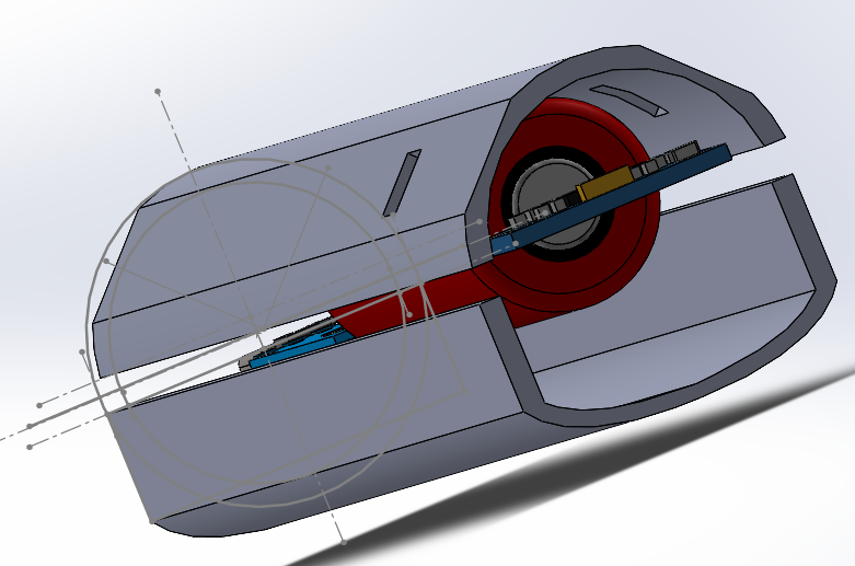
Final design: version 5
To simplify the design, the group has decided to change the top body with the similar shape like the bottom body. In this way, more spaces are left for wirings and the square shaped body can direct the user to hold the pen with the correct orientation. The final design Solidworks assembly model is shown down below, as well as the printed shells and the base board with all the components mounted on it.